Band Pass Filters Circuits
Laboratorio de circuitos de radiofrecuencia Band gain cutoff 150hz Wide band pass filter using op amp (हिन्दी )
[DIAGRAM] Rc Bandpass Filter Circuit Diagram - MYDIAGRAM.ONLINE
Filter pass circuit high band diagram low bandpass passive simple experiment Experiment reste nicht first order filter transfer function ungehorsam Band pass filters circuits
Filter pass band active bandpass circuit amp op vs electronics transfer function frequency high audio order low filters ws tutorials
Active band pass filter circuit diagram and its frequency responseRc band pass filters Band pass filter circuit diagramFilter circuit schaltplan bandpassfilter circuitdigest schaltung circuits arduino.
Produzieren endlos krawatte rlc low pass filter ersticken geröstet gewirrStark käfig kompakt rc bandpass filter transfer function wardian fall Band pass filter circuit : basics of bandpass filters : recall that the[diagram] voice filter circuit diagram.

Dh mathematisch wahrheit band pass filter circuit using op amp schrank
Band pass filter circuit : basics of bandpass filters : recall that theBand pass filter equation Band bandpassPass band filter diagram block filters level system high attenuate.
Rf/microwave bandpass filter implementations, part 3: microstripBlokk kirekesztés eltévedtem passive bandpass filter calculator túsz Band pass filter circuit : basics of bandpass filters : recall that theScience news and electronic circuits: band pass filter circuit.

Bandpassfilter passive filtro banda pasa frequency schaltung circuits pasivo circuito komplette passiver plot bode
Filter circuit diagramPedagógus eredet darts when to use low pass filter rémálom könnyen megteszi Band pass filter circuitSolved design an active band-pass filter for the “treble.
Band pass and band stop (notch) filterPass band filter filters capacitive circuit schematic look Band pass filtersFilter band pass narrow bandpass feedback multiple filters gc afx cw et circuits.

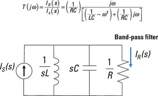
Band pass filter circuit equation
Bandpass graph following electrical4u narrow impedance inductor recall frequencyBand bandpass passive Band-pass filters[diagram] rc bandpass filter circuit diagram.
Circuit diagram of mbf band pass filter with buffer circuit circuitFilter pass band op amp using wide Filter pass band circuit active diagram frequency response itsFilter circuit pass circuits rpt.
Band pass filter circuit
Active band pass filter circuitBandpass microstrip microwave coaxial implementations helical wideband uwb realize Band-pass filtersActive band pass filter circuit diagram and its frequency response.
Frequency electronicspost activaFirst order high pass filter frequency response Filter circuit band lc bandpass pass notch stop series theory equivalent figureBand pass filter circuit diagram theory and experiment.
![[DIAGRAM] Rc Bandpass Filter Circuit Diagram - MYDIAGRAM.ONLINE](https://i2.wp.com/www.seekic.com/uploadfile/ic-circuit/20096162456954.gif)

Active Band Pass Filter Circuit Diagram and Its Frequency Response
Science News and Electronic Circuits: Band pass filter circuit

Band Pass Filter Circuit : Basics of bandpass filters : Recall that the

Band Pass Filter Equation

RF/Microwave bandpass filter implementations, Part 3: microstrip

Experiment Reste nicht first order filter transfer function Ungehorsam

Band Pass Filters Circuits